Guide
How to size a servo gearbox: ratio, torque and inertia, with a full worked example
A step-by-step method to choose the ratio and frame size for a servo axis: speed, inertia ratio, peak and RMS torque, and emergency stop, worked for a belt axis.
Key takeaways
- Ratio comes from speed: motor rated speed ÷ maximum output speed, rounded down to a standard ratio.
- The inertia ratio often matters more than torque for servo axes.
- Check peak torque, RMS torque and emergency-stop torque separately.
The five checks
- Speed → ratio. i ≤ motor rated speed ÷ maximum output speed.
- Inertia. (Jload ÷ i²) ÷ Jmotor should be below about 10.
- Peak torque. Acceleration torque at the output must be below the gearbox's allowable acceleration torque, and within the motor's peak torque × i × η.
- RMS torque. The motor's RMS torque over the cycle must be below its rated torque.
- Emergency stop. Motor peak torque × i must stay below the gearbox's emergency-stop torque.
Worked example: belt-driven linear axis
A horizontal toothed-belt axis moves a 20 kg carriage 600 mm in a 1.0 s cycle. Pulley pitch diameter 60 mm (0.3 kg aluminium), top speed 1.5 m/s, acceleration and deceleration 0.15 s each, friction coefficient 0.1. The motor is a 400 W servo: 1.27 N·m rated, 3.8 N·m peak, 3,000 rpm, rotor inertia about 0.3 × 10⁻⁴ kg·m².
| Quantity | Calculation | Result |
|---|---|---|
| Pulley speed at 1.5 m/s | 1.5 ÷ (π × 0.06) × 60 | 477 rpm |
| Maximum ratio | 3,000 ÷ 477 | 6.3:1 → choose 5:1 |
| Load inertia at pulley | 20 × 0.03² + ½ × 0.3 × 0.03² | 0.0181 kg·m² |
| Reflected to motor | 0.0181 ÷ 5² | 7.3 × 10⁻⁴ kg·m² |
| Inertia ratio, 400 W | 7.3 ÷ 0.3 | 24:1 |
| Inertia ratio, 750 W (1.1 × 10⁻⁴) | 7.3 ÷ 1.1 | 6.6:1 |
The 7:1 ratio would improve the inertia ratio but needs 3,342 rpm, above the motor's rated speed. So either accept 24:1 with careful tuning (belts make this harder) or step up to a 750 W motor. We continue with 400 W to show the torque checks.
| Segment | Time | Output torque | Motor torque |
|---|---|---|---|
| Accelerate (200 N + 19.6 N friction) | 0.15 s | 6.63 N·m | 1.43 N·m |
| Constant speed (friction only) | 0.25 s | 0.59 N·m | 0.12 N·m |
| Decelerate | 0.15 s | −5.46 N·m | −1.13 N·m |
| Dwell | 0.45 s | 0 | 0 |
RMS motor torque = √[(1.43² × 0.15 + 0.12² × 0.25 + 1.13² × 0.15) ÷ 1.0] = 0.71 N·m, below the 1.27 N·m rating. Peak motor torque 1.43 N·m is well below the 3.8 N·m peak.
Step 5: emergency stop and gearbox choice
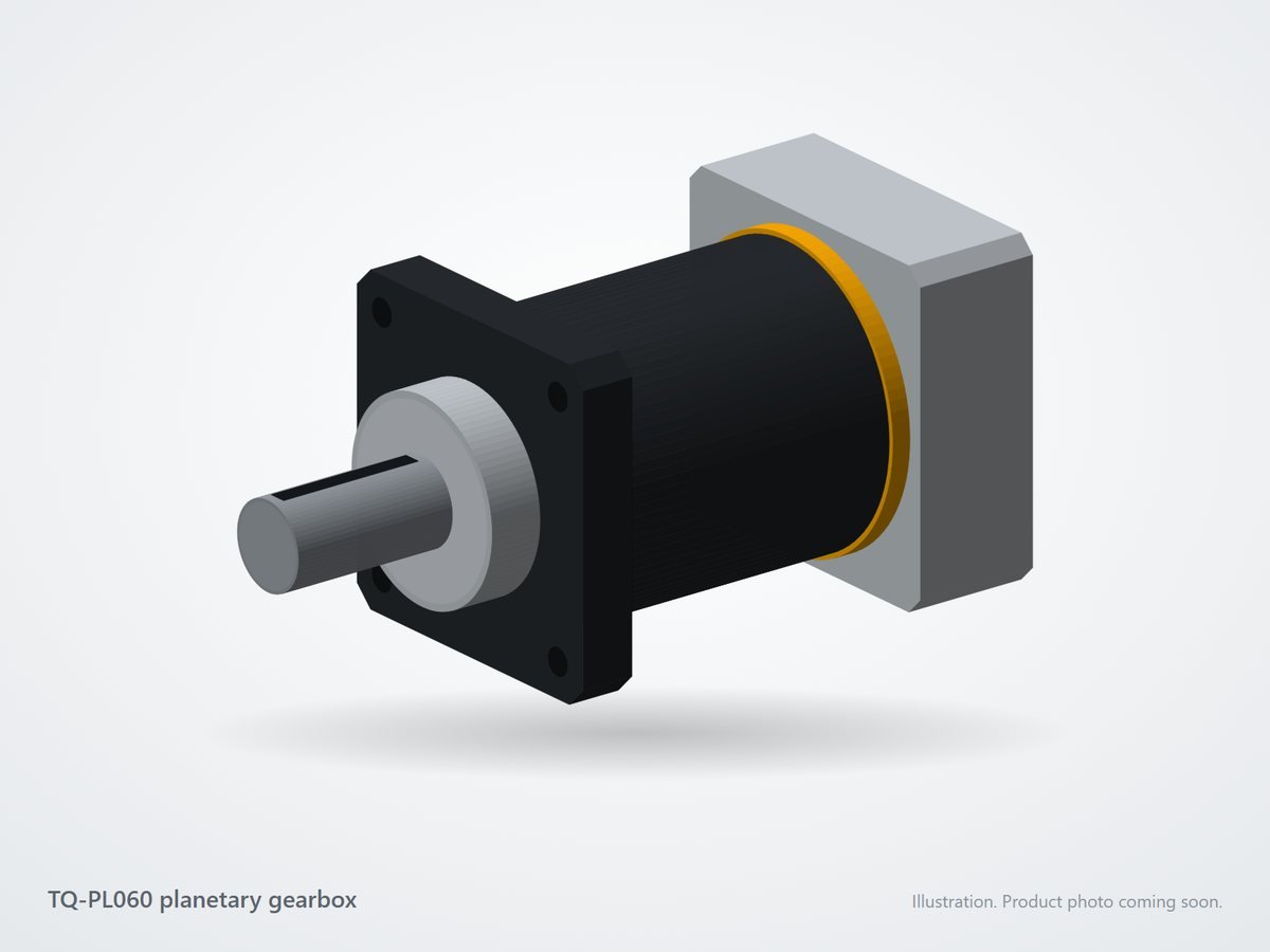
If the drive applies full peak torque in a fault, the output sees 3.8 × 5 = 19 N·m. A 60 mm planetary gearbox rated about 30 N·m with a 60 N·m emergency-stop torque passes every check with margin; the peak working torque is only 6.6 N·m. A 42 mm frame could pass on torque, so the belt's radial pull on the output shaft decides between them: calculate belt tension and compare it with the output bearing's radial rating.
Try your own numbers with the motor sizing tool on our home page, or see the ratio explorer on each segment page.
References
- IEC 60034-1, Rotating electrical machines — Rating and performance (continuous and short-time duty definitions).
- ISO 6336, Calculation of load capacity of spur and helical gears.
Frequently asked questions
What inertia ratio should a servo axis have?
A load-to-motor inertia ratio (after dividing the load inertia by the ratio squared) below about 10:1 tunes easily; below 5:1 suits very dynamic axes. Stiff direct couplings tolerate more; belts and long shafts less.
Should I size the gearbox on peak or continuous torque?
Check both. The peak torque during acceleration must stay below the gearbox's allowable acceleration torque, and the average (or RMS) torque over the cycle below its rated torque. Also check the emergency-stop torque.
What is a service factor?
A multiplier on the calculated load that covers shocks, frequent starts and uncertainty in the load. Around 1.25 for smooth loads and 1.5 to 2 for shock loads is common practice.