

 Zero-backlash class
 Cycloidal reducerFrame 110
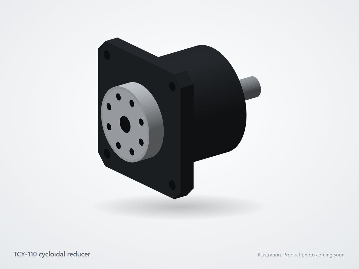
TCY-110 Heavy-Duty Cycloidal Reducer
- Rated torque
- 330 N·m
- Backlash
- ≤ 1 arcmin
- Ratios
- 11–119:1
from ₹64,000 + GST
In stockSingle-stage cycloidal reducers with ≤ 1 arcmin backlash, 500% shock capacity and a compact footprint. Ratios 11:1 to 119:1 for index tables, palletisers and heavy joints.
1 gearbox
Zero-backlash class Cycloidal reducerFrame 110
from ₹64,000 + GST
In stockNo gearbox matches these filters. Loosen the torque or backlash limit, or send us your requirement and we will build one.
Request a custom gearboxAdd or remove ring pins and watch the disc. It always has one lobe fewer than there are pins, and turns back one lobe per input revolution, so the ratio equals the lobe count: 12 pins give 11:1.
Turn on JavaScript to change tooth counts and see the ratio, output speed and torque update live.
Every cycloidal reducer can be joined to any motor, robot joint or housing: we machine a custom coupling bored to both shafts, plus an adapter flange if the mounting faces differ. Send both shaft sizes, a drawing or just the motor model number.
Get a custom couplingA cycloidal reducer has an eccentric cam on the input shaft that drives one or two lobed cycloid discs. The discs sit inside a ring of fixed pins, and each disc has one lobe fewer than there are pins. As the cam turns, the disc wobbles around the pin ring and, because of the missing lobe, rotates backwards by one lobe per input revolution. Output pins pass through holes in the disc and pick up this slow rotation. With 12 pins and 11 lobes, the ratio is 11:1; with 60 pins and 59 lobes, 59:1.
Cycloidal reducers work in rotary index tables, welding and painting positioners, palletising and handling robots, press feeders, machine-tool magazines, heavy AGV steering and joints that see frequent reversing under load. When you need higher ratio or even higher stiffness, compare with our RV reducers.
Calculate the peak acceleration torque of the axis and compare it with the acceleration torque rating, then check the average torque against the rated torque. For a rotary table, add the tilting moment from any off-centre load and compare it with the output bearing's allowable moment. Send us the table diameter, load mass and index time and we will recommend a size.
Direct-drive the table with a cycloidal reducer for stiffness, shock tolerance and accurate stops. Full worked example: inertia, index time, torque,…
A cycloidal reducer is a single cycloid stage driven directly by an eccentric on the input shaft. An RV reducer adds a spur-gear first stage and crankshafts. Cycloidal units are simpler and shorter; RV units reach higher ratios with higher stiffness.
Up to half the lobes of the disc are in rolling contact with pins at any moment, so an impact is shared by many contacts instead of one or two gear teeth.
At lower ratios, yes. At high ratios back-driving becomes difficult, so use a brake on vertical axes that must hold position with the motor off.
Typically up to 3,000–4,000 rpm depending on size. Check the average and maximum input speed in each product's specifications.