Application: Industrial robots
Gearboxes for six-axis robot arm joints: types, ratios and a sizing example
Which reducer goes in which joint of an articulated robot, typical ratios per axis, and a worked torque calculation for a 10 kg payload shoulder joint.
Key takeaways
- Joints 1–3 (base, shoulder, elbow) carry the arm's weight and tilting moments: RV reducers are the usual choice on industrial arms.
- Joints 4–6 (wrist) favour light, compact, near-zero-backlash harmonic drives, often with hollow bores for cables.
- Size on peak acceleration torque at full reach and full payload, then check average torque for life and the main-bearing tilting moment.
What each joint has to do
An articulated robot places its heaviest loads on the joints closest to the base. Joint 1 turns the whole arm, joints 2 and 3 lift it against gravity, and joints 4 to 6 orient the tool. Every joint needs a reducer that is stiff enough to hold the tool point, carries the moment from the arm, and survives an emergency stop at full speed. Because angular errors at a joint are multiplied by the arm's reach, a joint 2 reducer with 1 arcmin of lost motion moves the tool about 0.29 mm at a 1 m reach.
Typical reducer choice by joint
| Joint | Main load | Usual reducer | Typical ratio |
|---|---|---|---|
| J1 base | Arm inertia, tilting moment | RV (hollow for cables) | 120–160:1 |
| J2 shoulder | Gravity + acceleration, highest torque | RV | 120–160:1 |
| J3 elbow | Forearm + payload gravity | RV | 100–160:1 |
| J4 forearm roll | Wrist and payload inertia | Small RV or harmonic | 50–80:1 |
| J5 wrist bend | Payload moment | Harmonic | 80–100:1 |
| J6 flange | Tool inertia | Harmonic | 50–80:1 |
A seventh axis (a floor track) normally uses a planetary gearbox driving a rack and pinion.
Worked example: sizing a shoulder joint (J2)
Consider an arm reaching horizontally, the worst case for J2. The link masses below are simplified to point masses at their centres of mass.
| Item | Mass | Distance from J2 | Gravity torque | Inertia m·r² |
|---|---|---|---|---|
| Upper arm | 12 kg | 0.35 m | 41.2 N·m | 1.47 kg·m² |
| Forearm | 8 kg | 0.75 m | 58.9 N·m | 4.50 kg·m² |
| Wrist unit | 4 kg | 0.95 m | 37.3 N·m | 3.61 kg·m² |
| Payload | 10 kg | 1.00 m | 98.1 N·m | 10.00 kg·m² |
| Total | 34 kg | 235.4 N·m | 19.58 kg·m² |
- Dynamic torque. At a joint acceleration of 2 rad/s², inertia adds 19.58 × 2 = 39.2 N·m. Peak load torque is 235.4 + 39.2 = 274.6 N·m.
- Service factor. Applying 1.3 for control overshoot and model uncertainty gives 357 N·m. This must stay below the reducer's allowable acceleration/deceleration torque.
- Speed. A joint speed of 90°/s is 15 rpm. With a 3,000 rpm servo, the maximum usable ratio is 200:1; a 121:1 or 161:1 reducer leaves speed margin.
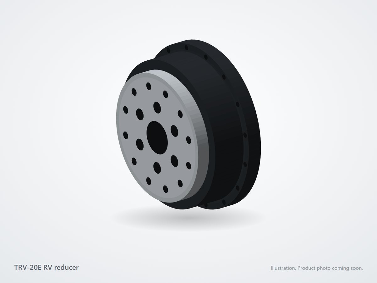
- Choice. A 20E-class RV reducer (allowable acceleration torque around 412 N·m, rated 167 N·m at 15 rpm) covers this joint, provided the average torque over the duty cycle stays near or below rated and the tilting moment from the arm is within the main-bearing rating.
A counterbalance spring or gas strut on J2 can remove much of the gravity torque and allow a smaller reducer and motor. For a full check, calculate the average torque over the robot's cycle and the resulting life, as shown in our service life guide.
Integration tips
- Mount the arm link directly on the RV output flange and use its main bearing; do not add a second bearing in series, which fights the first.
- Route cables through the hollow centre of J1 and the wrist harmonic drives to avoid cable wrap on continuous rotation.
- Keep the motor-to-input alignment within the gearbox maker's tolerance; misalignment is a common cause of noise and early wear.
We supply matched input flanges for your joint servos and custom joint housings that combine the reducer, motor mount and cable path. Send your arm's link lengths, masses and target speeds and our engineers will propose sizes for every joint.
References and standards
- ISO 9283, Manipulating industrial robots — Performance criteria and related test methods (defines pose accuracy and repeatability).
- ISO 9409-1, Manipulating industrial robots — Mechanical interfaces — Part 1: Plates (tool flange dimensions).
- ISO 10218-1, Robotics — Safety requirements — Part 1: Industrial robots.
Frequently asked questions
Why are RV reducers used in the base and shoulder of robots?
These joints carry the whole arm and payload plus large tilting moments. RV reducers have integrated angular-contact main bearings and very high torsional stiffness, so they hold the tool point accurately and survive emergency stops without a separate bearing.
Can I use a harmonic drive for a robot shoulder?
On light arms and cobots, yes: many cobots use harmonic drives in every joint to save weight. On heavier industrial arms, the lower stiffness and moment capacity of a harmonic drive usually makes an RV reducer the better choice for joints 1 to 3.
What ratio do robot joints use?
Most joints run between 50:1 and 160:1. Base and shoulder joints usually use the higher end (120:1 to 160:1) and wrist joints the lower end (50:1 to 100:1), depending on motor speed and required joint speed.